How Waveguide Phase Shifters Work: Types and Key Applications
When microwave engineers talk about steering beams or fine‑tuning radar links, waveguide phase shifters are often at the heart of the discussion. These devices manipulate the phase of a signal traveling inside a hollow metallic waveguide without converting it to a coaxial line or a semiconductor medium. By introducing a controllable delay, they enable everything from phased‑array antennas to frequency‑agile transmitters. Below we unpack the underlying physics, walk through the most common architectures, and explore where these components shine in today’s high‑frequency systems.
How Waveguide Phase Shifters Work
The basic principle hinges on changing the electrical length of the waveguide. A signal propagates at a speed determined by the guide’s dimensions and the dielectric filling (usually air). If you can make the wave travel a little farther—by adding material, altering geometry, or shifting resonance—the output phase lags behind the input. The amount of lag, measured in degrees or radians, is the “phase shift.”
Three physical mechanisms dominate:
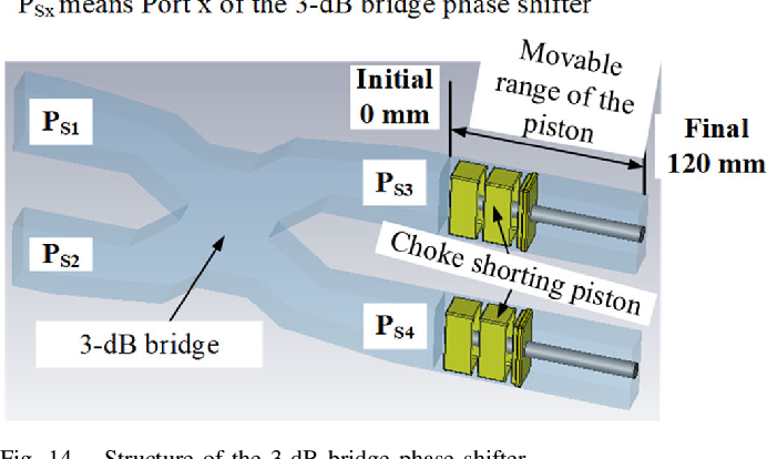
- Mechanical insertion: A metal plunger or a movable short-circuit is slid into the guide, extending the path. The further the plunger, the larger the shift.
- Electronic loading: Magnetically tunable ferrite slabs are placed inside the guide. Applying a bias magnetic field changes the ferrite’s permeability, which in turn tweaks the propagation constant.
- Dielectric loading: Low‑loss ceramics or polymers are introduced; varying temperature or applying voltage modifies their permittivity, adjusting phase.
Because waveguides operate at frequencies where wavelengths are only a few centimeters long, even a millimeter of extra path can produce a 30‑degree shift. This sensitivity is why waveguide phase shifters deliver fine resolution and high power handling compared with their coaxial or solid‑state cousins.
Common Types of Waveguide Phase Shifters
Designers choose a type based on power level, bandwidth, speed, and control simplicity. The main families are:
- Mechanical (or rotary) shifters: Often called “trombone” shifters, they use a movable short or a sliding waveguide section. Their advantage lies in broadband performance and near‑lossless operation, but they are bulky and relatively slow—suitable for test equipment or satellite ground stations.
- Ferrite‑based shifters: A slab of ferrite sits in the guide, and a bias coil creates a magnetic field. Adjusting the coil current changes the material’s permeability, yielding a continuously variable phase. They handle high peak powers (tens of kilowatts) and can be switched in microseconds, making them popular in phased‑array radar.
- Electronic (solid‑state) shifters: These incorporate PIN diodes or varactor diodes across small apertures in the waveguide wall. By biasing the diodes, the effective capacitance changes, altering the guide’s electrical length. They excel in fast switching (<100 ns) and integration with digital control, though they typically support lower power than ferrite devices.
- Dielectric‑tuned shifters: Low‑loss dielectric inserts, often made of ceramics like barium strontium titanate, can be heated or voltage‑biased. The phase shift tracks the permittivity change. This approach offers moderate speed and very low insertion loss, useful in precision measurement rigs.
Hybrid designs also exist—for example, a ferrite slab paired with a mechanical plunger—to combine fine‑step resolution with a wide tuning range.
Key Applications in Modern Systems
Waveguide phase shifters are not a niche curiosity; they underpin several high‑performance technologies.
Phased‑Array Antennas
In both airborne radar and ground‑based surveillance, each antenna element needs a slightly different phase so the overall beam points where desired. Ferrite or solid‑state shifters, embedded directly behind each radiating slot, allow rapid beam steering without moving the entire antenna structure.
Satellite Communications
Satellite transponders often require phase alignment across multiple feed horns to maintain signal integrity. Mechanical shifters, with their low loss and broad bandwidth, are favored in the uplink and downlink paths where power levels can exceed 100 W.
Microwave Test and Measurement
Calibration rigs and vector network analyzers use precision rotary shifters to introduce known phase offsets. Their repeatability (better than 0.1°) helps verify the performance of other components.
Electronic Warfare and Counter‑Measures
Fast electronic shifters enable rapid frequency hopping and phase scrambling, confusing hostile receivers. The nanosecond switching times of diode‑based designs make them ideal for pulse‑compression radars that need to change phase on a per‑pulse basis.
High‑Power Microwave (HPM) Sources
When generating megawatt‑level pulses for research or defense, the waveguide network must survive extreme fields. Ferrite shifters, with their robust thermal handling, are often the only viable option.
Choosing the Right Shifter for Your Project
Start by ranking your priorities:
- Power handling: Above a few kilowatts? Ferrite is usually safest.
- Bandwidth: Need >10 % fractional bandwidth? Mechanical or dielectric shifters typically outperform solid‑state variants.
- Switching speed: For sub‑microsecond agility, electronic diodes win.
- Size and weight: Space‑constrained platforms (e.g., UAVs) often opt for compact solid‑state modules.
- Control complexity: Mechanical devices are simple to drive with a motor; solid‑state units integrate cleanly with digital logic.
Balancing these factors will guide you to the architecture that delivers the needed phase range (often 0–360°) while staying within loss, linearity, and reliability budgets.
Frequently Asked Questions
What is the typical insertion loss for a waveguide phase shifter?
Loss varies by type: mechanical shifters can be as low as 0.1 dB, ferrite devices usually sit around 0.2–0.5 dB, while solid‑state shifters may reach 1 dB or more, especially at the high‑end of X‑band.
Can a single phase shifter cover the full 0–360° range?
Yes, most commercial designs provide continuous 360° coverage, either through a full rotation of a mechanical plunger or by combining two 180° sections in a ferrite or electronic module.
How temperature affects performance?
Temperature shifts the permittivity of dielectrics and can alter ferrite permeability. High‑precision systems therefore include temperature compensation circuits or use materials with low temperature coefficients.
Are waveguide phase shifters compatible with planar circuits?
Directly, no. However, transitions (waveguide‑to‑microstrip) allow integration with planar phased‑array modules, letting designers exploit the low loss of waveguides while leveraging modern silicon‑based control chips.